<<-- Back Repairing the Dec/RA Drive Next -->>
Return to Bruce Johnston's homepage
Onward to the Electronics Board
We can now look at the final general area of the drive units; the small electronics board that's mounted on it, and its components.
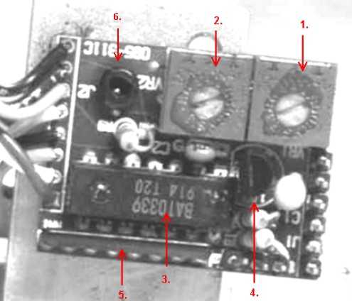
In this first picture (shown with the board upside down because that's how it looks when it's mounted) , there are five components that are pointed out so that you'll begin to know the layout of the board. The components are:
1. Variable resistor, or potentiometer #1. This resistor will be used to allow us to adjust the triggering level for comparator #1. (We'll call it the comparator that gives us the BLACK square wave shown earlier.)
NOTE*: The numbers used for the comparitors is arbitrary. They were selected simply as a convenience and have no electronic significance.
2. Variable resistor, or potentiometer #2. This resistor will be used to allow us to adjust the triggering level for comparator #2. (We'll call it the comparator that gives us the RED square wave.)
3. This component contains the two actual comparators that are used in the circuit, comparators #1 and #2. There are four of them in this package, but only two are used.
4. This is a +5 volt voltage regulator. The main voltage for the scope, either +18 or +12, depending on the operation of the scope, is fed into this little chip and +5 volts comes out. The voltage is used to power the LEDs and light sensors that are connected to the board.
5. This is a 'resistor pack'. That means that multiple resistors are housed in one package. I show this because some people with limited electronic experience may only be familiar with individual resistors.
6. This is the allen screw that holds the board in place. Beneath it is a small insulator. If the screw is removed in order to service the board, watch for this small circular insulator. It must be put back in place to keep the components from shorting out on the metal plate it mounts on.
There are several more components ... resistors and capacitors ... also on the board, but in general, you won't be dealing with them for normal failures.
The connector pins

The connector pins are labelled down the right side of the image. This list isn't just for general information; you'll want to know their specific purpose when you trouble shoot and repair the unit. The purpose of the pins are:
1. Output signal from comparator #1. It is the 'square wave' signal that's sent back to the main logic board to be used for determining motor speed and direction. (By the description of it's use, this should be a hint to you that it has a LOT to do with motor runaway !! )
2. Output signal from comparator #2. It supplies the same information from comparator #2 as does pin #1 for comparator #1.
3. This pin is used only on the R.A. drive assembly, and sends a signal back to the main logic board from the magnetic pickup. When the magnet activates the magnetic sensor, this line will supply a 'low', or zero volts. The rest of the time, it is 'floating', or disconnected.
4. The + 12/+18 volts from the power supply is brought to our board on this pin.
5. This is the 'ground', or zero volt line from the power supply.
6. This line also is the 'zero volt' line from the power supply. However, on any boards that I've seen that are used in the R.A. unit , there is no wire connected to it. This would explain why the mother board connector end of the cable only has seven connections on it.
Notice that there are no pins available for motor connections. Instead, they go directly from the motor, around the connector, and into the cable.
Test point pins
7. Another ground, or zero volt line. It's a convenient place to attach a meter or the ground from an oscilloscope.
8. The output from the light sensor that is the input signal to comparator #2.
9. The output from the light sensor that is the input signal to comparator #1.
Board shown with output/input connector attached.
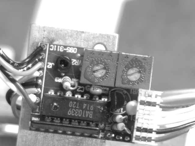
This view is simply to show you the complete board, with the six pin input/output connector attached. (A potential source for problems in itself!! )