Superwedge Modifications by Dave Schanz
If you own a Meade SuperWedge then I don't need to tell you it's a real piece of work. It seems to be an excellent design,
just poorly executed. Like everything else Meade,
it requires some tweaking to make it work as it should.
I must say that I was a bit skeptical when I read so many MAPUG members telling their horror stories about the wedge. I honestly
didn't think it could be all that bad. So, last winter, I saw one for sale at a good price on Astromart so I bought it. When
it arrived, it looked sturdy and well made.
I figured perhaps some of the criticism was unfounded.
In the fall of 2001, I installed the pier and was ready to try out the wedge. With great excitement and anticipation I carefully
leveled the mounting plates on the pier, mounted the wedge and then the scope. Finally, after many months of waiting, I was ready
to polar and drift align the scope and begin working toward my adventures in astrophotography. I read up on polar alignment,
figuring it would be a snap, and I was prepared to take the time
necessary to do it right.
The first clear night came along and I was ready. I roughly pointed the scope at Polaris according to the instructions in the
manual and then began the polar alignment routine. Looking through my 12mm reticle EP, Polaris was visible in the EP but outside
the center box of the crosshairs. No big deal I thought, a little tweaking of the AZ knob and the latitude knob and that would
be it.
Big surprise. I turned the AZ adjustment knob and Polaris moved a hair in the EP. A tiny bit more of a turn on the knob and
- nothing. Turned it a bit more - nothing. Then, with a little bit more of a turn - Polaris shot across the field of view and
completely disappeared! Same results with the latitude adjustment. I tried for almost three hours but could only come close to
centering Polaris in the crosshair box of the reticle
EP. I gave up in disgust and went inside for the night.
The next morning, I took a good look at the mechanical operations of the wedge. There was slop everywhere. Nothing fit even
close to snugly. In the latitude adjustment assembly, I turned the knob and took up the slack just until the tilt plate moved.
Then, reversing directions, I noted it took from 1 to 3 full turns before the slop was taken up and the tilt plate moved. I had
the same results with the azimuth adjustments. It was quite frustrating. The azimuth dog even had a lot of slop in it. Grasping
the pin on the bottom of the dog, the dog wiggled back and forth
at least .020". It was all unbeliveable.
It is worth mentioning here that to my knowledge, the wedge had not been modified by the previous owner. I can't be positive
of that because I didn't ask the previous owner, and I have never seen one before in person so it is hard for me to tell for
sure.
In the months between the time I bought the wedge and the time I actually used it, I spent a lot of time visiting web pages
of MAPUG members who had modified theirs. The MAPUG archives has many articles about wedge mods too. Then, there are alternative
wedges from Milburn and Mettler. I gave it considerable thought and decided to try and fix the problems with the Meade wedge
- basically, rebuilding it the way Meade should have built
it in the first place.
THE AZIMUTH DOG 
The first issue I tackled was the azimuth dog.
As I said, it was very loose on the 1/2" threaded rod. I needed to turn the hand knob about 1/2 to 1 full turn just to take
up the slack before the dog would actually begin to rotate
the wedge on its axis.
To fix that, I copied an idea I saw on someone's wedge modification web page. (I am very sorry that I don't have the designer's
name to give him the credit he deserves here.)
The az dog mod involves using four 1/2" nuts and a bunch of JB-Weld. The original design called for simply using JB Weld
to add 2 nuts to each side of the AZ dog, effectively making it
into a "T". I modified that mod a bit by using a few reinforced cut-off wheels in my moto-tool and cutting large flats
on the top of the dog so the nuts would fit flush.
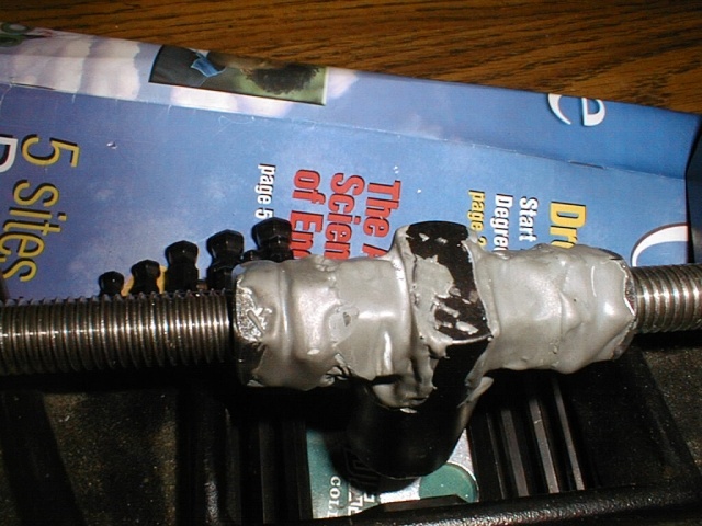
This is a photo of the azimuth dog after I cut it down to mount nuts flush to the face and stick the whole thing together with
JB Weld. The extra length gives the dog much more stability so it doesn't wobble on the threaded rod any more. It isn't pretty,
but it works great! If you make this mod, make sure you assemble the whole thing on the threaded rod before adding the JB Weld
to keep it all in line. Take your time with your moto-tool and reinforced cut-off wheels when cutting the dog down to size.
I used 3 wheels to cut this stuff. Be careful too. Make sure you put some sort of oil on the threaded rod to prevent any JB
Weld from sticking to it.

This is the back view of the azimuth dog after modifiying it. Note the shape of the dog where I cut
out about 1/3 of its
original diameter so the nuts would fit flush.

This is the view from inside the front of the wedge with the newly modified azimuth dog. You can plainly see
(I hope) how I
cut the top of the round dog to give 2 flats where the nuts are JB welded to the dog.
You can clearly see in the enlargement how I cut the top of the AZ dog to accomodate the nuts. That gives a flat surface so
the JB Weld can do it's thing. I suppose it is worth noting it is important to assemble the whole thing on the threaded rod to
make sure everything is properly aligned prior to slopping on the JB Weld. Just to be sure the JB Weld wouldn't stick to the
threaded rod, I sprayed the rod with a little PAM (butter flavor!) first and then assembled the nuts and dog. Also make sure
you leave about 1/16" inch space between the nuts
so they don't act like jam nuts. Let the JB Weld dry overnight.
When the JB Weld is dry, try to turn the assembly on the threaded rod. It should turn, but not very smoothly. On mine, there
were several areas along the length of the threaded rod where the dog wouldn't turn at all. I put a couple of jam nuts on one
end of the threaded rod and using a box end wrench, I ran the dog assembly from one end to the other what seemed like a hundred
times until it eventually moved back and forth as smooth
as could be. You're done with the azimuth dog!
AZIMUTH ADJUSTMENT ASSEMBLY
The next chore I tackled was the entire azimuth adjustment assembly consisting of the dog, the threaded rod and the hand knobs.
What a mess that was. There was slop everywhere. The holes drilled through the castings for the threaded rod were way oversize.
This allowed for approximately
.030" wiggle room between the threaded rod and the walls of the hole. Also, the knob didn't turn smoothly. When the knob
was turned, there was one area where it required almost Herculean effort to turn beyond that point - even then, the knob got past
the tight spot all at once. There was no way a fine adjustment
could be made, no matter what.
Here's what I did: At Ace Hardware,
I found brass bushings that fit the threaded rod snugly. The bushings
are 1/2" ID x 11/16 OD x 1" long. The holes in the side
castings of the wedge are roughly 1/2" so I needed to enlarge
them to 11/16". I had to buy an 11/16" drill. If you have a friend or relative with a bench or pedestal mounted drill
press, you're in business (they may even have an 11/16" drill too!) DO NOT ATTEMPT TO DRILL OUT THESE HOLES USING A HAND
DRILL! You will screw up the holes, guaranteed! Normally, enlarging holes is a difficult task at best, but the castings are aluminum
which
is relatively easy to drill and a drill press is sturdy enough
to enlarge the holes without ruining them.
I drilled the 1/2" holes
oversize to 11/16" using my drill press. With a few taps of a hammer, the bushings slid into the holes cleanly. The bushings
were about 1/8" too long but that was good as it would provide a flat surface for the thrust bearings I would assemble later.
I left the extra length of the bushing sticking out on the INSIDE
of the wedge side plate castings.
I bought 6 thrust bearings from McMaster-Carr, 4 for where the az threaded rod passes through the side plates and 2 to use
later on the latitude adjustment bar. Now, I assembled 2 jam nuts and a thrust bearing on each end of the threaded rod and assembled
the side plates and base plate. I then assembled an additional thrust bearing and 2 more jam nuts and the knob on each end. I
carefully tightened the inside jam nuts against the thrust bearings which mated against the brass bushing (remember the bushing
is longer than the side plate is thick? It provides a nice, flat mating surface for the thrust bearings!). I then tightened the
outside jam nuts against the outside thrust bearings and assembled the knobs.
The assembly works like a charm! There is absolutely no backlash whatsoever in the azimuth adjustment!
This view shows the bushing protruding out of the casting so the thrust bearing
(the red washer) has a flat
surface to ride against.
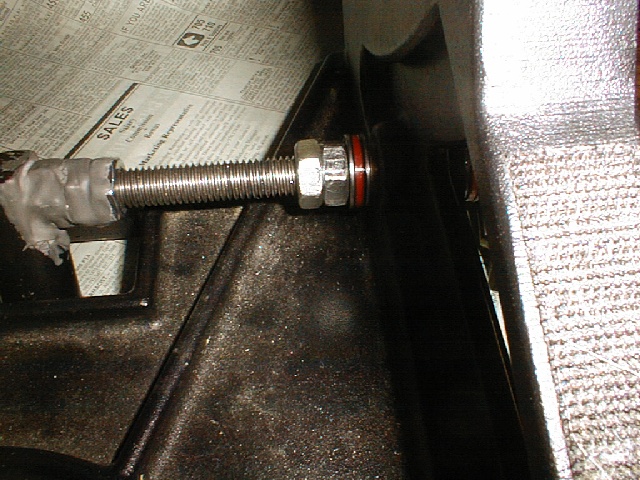
In this view, you can see the 2 jam nuts and the red thrust bearing with steel washers
on each side
(they came with the bearing). You can also see the brass bushing extending about 1/8"
through the side plate casting which provides the flat surface for the bearing to mate to.
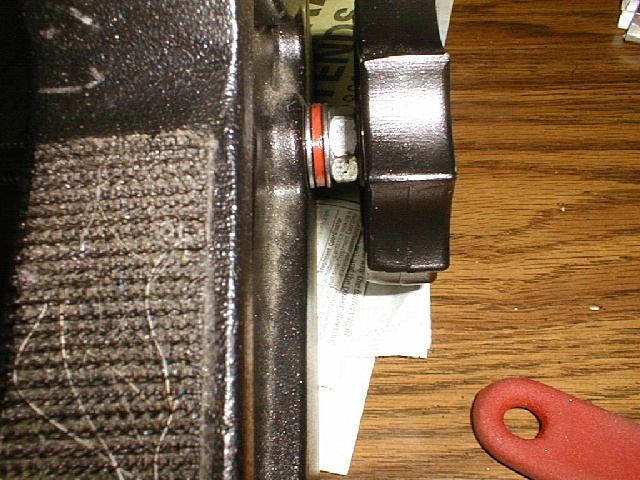
In this picture, you see the hand knob, jam nut, and
the thrust bearing with the two steel washers on either side.
LATITUDE ADJUSTMENT ASSEMBLY
Perhaps the worst part of the wedge design, the latitude adjustment mechanism assembly had slop everywhere. I measured .025
clearance between the 1" round aluminum latitude adjustment bars and their corresponding holes in the wedge. That causes
untold frustration when trying to do a fine adjustment since the slop has to be taken up as backlash when reversing directions
with the hand knob. On top of that, the bar flexed considerably when the tilt plate is tightened down and the knob was turned
adding to the backlash problem.
So, my analysis of the backlash when the direction I turned the knob is this: First, the slop in the holes where the bars sit
is taken up. Then, the threaded rod moves from one side to the other inside the untapped hole in the lower bar because of the
extra clearance, and lastly the bar flexes until the friction between the side plates and tilt plate is overcome. Then and only
then the tilt plate finally moves - usually with a jerk as pent-up energy is released. Clearly, there were several issues that
needed to be addressed.
First, I put shims between the bars and their corresponding holes to take up the excess play. That helped some but it was no
complete cure. What I needed, was a stronger lat adjustment bar - one that wouldn't flex and would also provide a flat surface
for the thrust bearings to mate to. I knew a square bar, not a round one, was the answer. I was fortunate enough to have a father-in-law who has a neighbor
with a metal lathe in his garage. I took a trip to my local scrap
yard and picked up a piece of 1-1/2" square cold rolled steel
bar stock 12" long for $7.00. A 1-1/2" square bar is
a serious piece of metal! They didn't have 1-1/4" bar or I would have used that. Anyway, no way was this bar going to flex
on me!
Careful measuring of the holes in the end plates that accept the bar showed the holes were actually tapered. The bottom of
the holes were 1.015" and the top edge of the holes
were 1.025"! It was clear the best answer would be to bore out the holes, press in a bushing, and bore the bushing to accept
the shaft with a nice tight fit! But, that was not to be as I
don't have access to that kind of equipment.
To make it work as well as possible, I had
the neighbor turn the ends of the bar to 1.010" and I filled the variable size gap with shim stock. He did a nice job turning
the ends of the bars to the dimensions I provided. He also drilled
a 1/2" diameter clearance hole for the threaded rod to pass
through.

This is a shot from above the lat adjustment knob. I have replaced the round aluminum bar with a 1-1/2" square
bar with turned down ends. I have shims on both bars where they enter the holes. The top bar has duct tape holding the shims
in place.
At some point, I will paint the square bar flat black and replace the duct tape with some electrical tape. The large, manly
square bar removes all of the flexure I had in the aluminum bar and the shims remove all the slop in the holes in the castings.
Both
of those items are significant contributors to backlash.

This is a picture of how I resolved the excessive play between the holes in the casting and the lat ajdustment
bars. Okay, the bright camera flash washed out the blue color of the shim stock (the blue you see is the reflection off the
black casting) but they are really blue. I simply cut off appropriately sized lengths of a 5" x 20" sheet of polyester
shim stock (McMaster-Carr) and inserted them in the gaps. The plastic (polyester) shims are very smooth and slippery and the
rods rotate great!
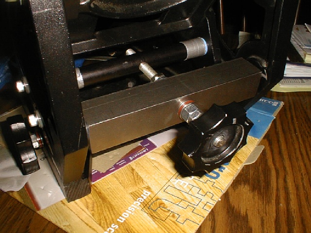
In this view, you can see the red "washer" which is actually a thrust bearing. There is an identical
set on the other side. This provides a silky smooth movement of the knob and there is 1/4 turn of backlash when the knob direction
is reversed. The source of the remaining backlash comes from too much clearance where the turned down end of the bar fits into
the hole. I will add additional shims there this week to remove the last of it. That portion has been a trial and error method.
As you can see, the 1-1/2" square bar is a manly piece of iron at 6 lbs or so! There is no way on earth it will flex when
I turn the knob, even with the side adjusting
screws tightened down significantly.
I also installed thrust bearings between the bar and the jack screws. The thrust bearings are the red washer-looking item in
the above picture (make sure you click on it to see the bigger version). The assembly now works smooth as silk. There is still
about 1/8 turn of backlash in the movement, but that is because there is still some slop between the shaft and the hole. I will
try to shim that some more in the next few days to
remove the last of it.
I am very pleased with this mod and only wish Meade would have followed this path instead of using the cheesy round aluminim
bars.
My next wish, is to have the holes in the side
plate bored out, bushed and the bushings bored to fit the shaft
snugly.
TOTAL COST OF THE MODS - $53.30
(not including the cost of the 11/16" drill which will become
a part of my tool box.)
I am very happy with the results, although a bit perplexed why I had to do it in the first place. If I can fix the wedge for
about $50.00, they should be able to
do it better for cheaper. So what's the deal with Meade?
I would once again like to thank everybody's wedge web pages I visited and the contributors to the articles on modifications
in the MAPUG Topical Archives. I borrowed liberally of course, but fail to mention their names in these pages because I didn't
note them over the months of research and
for that I apologize profusely.
If you have any questions about these mods,
please feel free to email me at <dave23sch at  valleytranscription.com> valleytranscription.com>


|
