
Construction Details for the
Heath Pier and Mounting Plates


By Andy Heath, <andy.9.heath gsk.com> <andyheathcwctv.net>
Also see: Observatory Plans, Wedge Modifications and Permanent Piers.
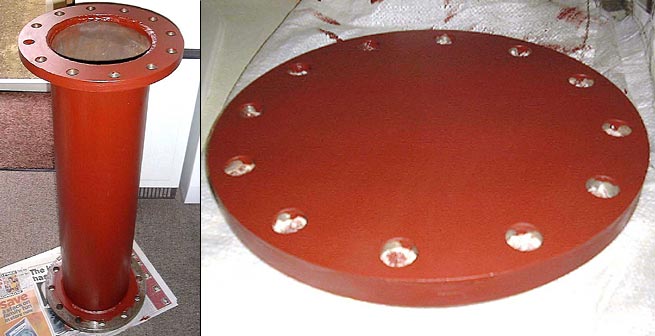
Figures A & B
Pier Tube: fig. A-- The pier tube is a piece of pharmaceutical grade seamless 8" diameter x 3/8" walled steam pipe. A jointless pipe that was extruded when manufactured.
Top & Bottom Pipe Flanges: fig. A & B-- Two 8" diameter x 1" thick solid steel pipe flanges were reverse fitted to the pier tube, this was for the small collars to fit inside the main tube and act as an extra keying point when being welded. Both pipe flanges were welded both inside and out for extra strength.
Flange Blanks: fig. B-- Two 8" diameter x 1" thick pipe flange blanking plates were used to seal off both ends of the tube. The bottom flange blank was bolted onto the pier tube flange using A4 grade M20 stainless steel nuts, bolts and washers, leaving four holes open to mount the structure onto the ‚Jç bolt studding when finished. The top flange blank had a hole drilled through the centre to allow the original tripod bolt to be used. This was welded in place on the underside of the blanking plate and for extra security a nut was also placed on the underside of the rod and tightened up to the weld. As you will see from the image the top flange has had its centre bored out to a depth of around 1.5-2mm deep, this is for the Super Wedge adapter plate to sit in. When this recess is greased up it behaves like a bearing enabling the whole Super Wedge to be rotated through 360 degrees. The reasoning behind this was that by doing this we didnçt have to worry too much about aligning the ‚Jç bolt studding too much or the pier orientation at the concreting stage. It also means that I can never run out of azimuth adjustment as can happen when the scope sits Polar mounted on the tripod. Four holes were evenly spaced drilled and tapped to accept the clamps to hold down the Super Wedge adapter plate.

Figures C & D

Figure E

Figures F & G
Super Wedge Adapter Plate: fig. D, E, F & G-- The wedge adapter joins the pier top to the Super Wedge and is constructed from a solid piece of 8" diameter aluminum. It has been drilled through the center for the original tripod bolt to travel through. This adapter plate has been machined at the bottom to fit snuggly into the recess of the bored out top flange blanking plate, it also has a machined ledge around 1.0" high that four stainless steel ‚L' shaped clamps bite on to secure it in place. These are secured with four M16 cap head Allen bolts that secure down into the four threaded holes in the top blanking plate. I cut four small strips off of an old Dycem non-slip mat and stuck them to the underside of the 'L' shaped brackets for extra grip and to avoid damaging the finish of the aluminum. A tapered lip was machined at the top of this adapter plate to enable it to mate correctly with the underside of the Super Wedge, (the Super Wedge was also machined underneath to accept the tapered top), when greased it acts as a bearing surface for the fine wedge adjustments that need to be made. The wedge adapter utilizes the 'T' dog V block (see fig. L) that I removed from the tripod, the top of the adapter has the three threaded holes for the three extra wedge bolts used to secure the wedge down.
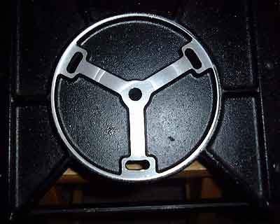
Figure H
Super Wedge: fig. H-- The Meade Super Wedge has had its underside skimmed to remove any irregularities in the casting and as mentioned above it has a machined lip around the outside of the circular casting to accept the adapter plate above. The 'T' dog (see fig. L) has been modified and now gives zero backlash when doing fine adjustments for Polar alignment. A threaded bolt-ended sleeve was placed over the original studding and it screws into the 'T' dog on one side. As it is tightened gently the sleeve splits out putting a small amount of pressure on the internal thread of the 'T' dog eliminating the more than evident play that was there. Having a bolt type end to it this sleeve is fully adjustable.
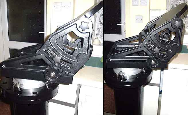
Figures I & J
Pier, Adapter & Super Wedge: fig. F, G, I, J & M-- In these images you can see how the three components all fit together.

Figures L, M, & N
‚Jç Bolt Pier Mounting Template: fig. N-- Firstly I made two plywood rings by drawing round the pier tube flanges before they were welded to the tube, including all of the bolt holes and marked both the flange and the templates for the correct orientation once it was set in the concrete. Four three feet lengths of A2 grade M20 stainless steel studding were heated and bent to form the infamous ‚Jç bolts. Using several stainless steel nuts and washers, you can see that the two templates were placed apart and bolted down to leave the correct amount of studding which would protrude from the concrete footing to mount the pier and allow for the nuts that would be used beneath the pier for leveling purposes. In the image you can see the upside down pier with the template temporarily in place as a final check for the best fit before setting it in the concrete footing.
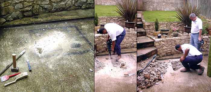
Figures 1, 2, & 3
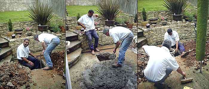
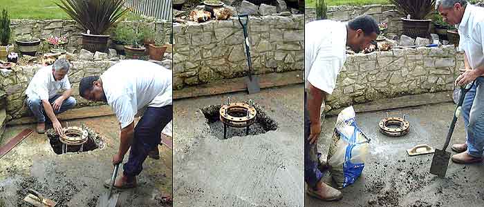
Pier Base Footing: fig. 1, 2, 3, 4, 5, 6, 7, 8 & 9-- I have a solid concrete footing to contend with and I did get lots of advice from fellow MAPUGGERS and others on the best way to handle possible vibration problems that might occur. I decided that I would get the local builders in to do this part for me, as I wanted it done properly and quickly as it was early October and I was in fear of the weather changing as it does so readily in the UK. The existing patio concrete was almost 5" thick and I wanted a 2.5ç x 3ç deep hole dug in it! I had previously marked out the position of where I wanted the footing to be. I was more than a little nervous because to sight Polaris the footing had to be dug rather close to a surface rain water gully and drainage pipe that runs directly underneath it. As luck has it my worries were totally unfounded and everything went to plan for a change. A small Kangol was used to break up the existing surface down to a rather wet two feet or so of clay. Mixed in with this clay were some of the biggest flints I have ever seen some were over a foot long and 8" across, these had to be prized out using a crowbar! After the 2.5ç of clay the chalk layer was finally hit and a base of 4-6" of 3:1 concrete mix was laid as the foundation for the ‚Jç bolt template to sit on. Caption continued below:
Figures 4, 5, & 6
Figures 7, 8, & 9
Caption continued-- Once the template was propped and leveled the rest of the 3:1 mix was placed in around it, tampered down to remove any air bubbles, and filled up to the underside of the first wooden part of the template and then finished off. Expansion board was used to isolate the concrete footing from the surrounding patio to help remove and reduce any surrounding vibrations from reaching the pier footing.
The pier base was then covered in polythene to avoid it drying out too quickly and also protect it from the odd shower that had been plaguing the builders on and off all morning. I left it for a week like this before uncovering it, undid the nuts and removed the wooden templates leaving the studding protruding from the footing. Thanks to this template the studding was accurately placed to receive the pier in all of its glory. Firstly I placed one A4 grade stainless steel M20 nut on each of the four pieces of studding and wound them down until they were about 0.5" from the ground, followed by two stainless steel A4 grade M20 washers on each piece of studding. I then had to sweet talk my wife Sam into helping me lift my rather heavy super structure pier onto the studding until it came to rest on the nuts and washers that I had just placed on the studding.
One excellent tip here, when leveling the pier I used a digital level that has an audible beep on it which goes off when level. So I was on my hands and knees with spanners adjusting the pier until the level sounded and I was all done in both directions.
Before bolting down the top flange blank I poured two 25Kg bags of kiln dried sand into the pier to dampen any vibrations that may occur. The top flange was bolted down using several A4 grade stainless steel M20 nuts bolts and washers. Both top and bottom flange blanks had a bead of Silicone placed around the mating surfaces to avoid any ingress of moisture reaching the kiln dried sand inside.
The painting of all the component parts were done before assembly, all of the steel parts received two thick coats of Red Oxide primer all over, even on the inside of the bolt holes in the flanges and blanking plates.
This was followed by three thick coats all over of flat black Hammerite paint, (flat as opposed to the hammered finish), this gave the pier a very deep gloss shine and the nature of this paint left it feeling like the pier has a plastic type coating on it so it should easily survive the English bad weather!
The Full Monty!
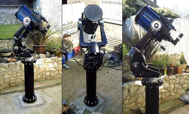
The Full Monty From Three Perspectives: Here you are able to see the finished ‚super structureç with my 10" LX200 Classic mounted on it. This pier is extremely stable and more than capable of handling a much larger scope than the 10" should I ever win the lottery!
Very Special Thanks
Very special thanks must go out to Peter Sullivan of The Birch Grove Observatory who was one of the very first guys to contact me after my original posting to MAPUG. Pete very kindly was on hand at all times to answer my endless questions and thoughts that I had on this project. I had never attempted anything of this magnitude before and can honestly say that I couldn't have done it without his help. I consider Pete to be a good friend and remain in regular contact with, well I try, when his system isn't down! Havençt you fixed that yet Pete?!!
I would also like to take this opportunity to thank everyone else who took the time to respond to my questions with their own thoughts and experiences and of course a big thank you is also in order for the person who maintains the MAPUG Topical Archives, Ed Stewart, thank you. MAPUG has a wealth of information at our disposal and it is great to know that we LX200 owners have this information so readily at hand for our personal use.
If anyone is thinking of taking up a project like this I would thoroughly recommend it. If anyone has any questions,
thoughts or remarks on my pier project please feel free to ask or comment as all feedback is good feedback. Thanks for browsing
over this, I hope that you enjoyed it.
Best Regards, Andy Heath
Nil Satis Nisi Optimum (Nothingçs Satisfactory Unless Itçs The Best!)
Return to Permenant Piers page.